 Περιγραφή Εγκατάστασης Παραγωγής Ατμού
Το σύστημα λειτουργεί σε δύο κύριες καταστάσεις (modes):
α) Άντληση φορτίου (Cargo pumping)
Ο Λέβητας Καυσαερίων / Economizer και η στροβιλογεννήτρια (TG) βρίσκονται συνήθως εκτός λειτουργίας. Η πίεση ατμού του δευτερεύοντος τυμπάνου ατμού ρυθμίζεται περίπου στα 13 bar, παρέχοντας ατμό στις στροβιλοαντλίες φορτίου, με δυναμικότητα περίπου 50 t/h. Η πίεση του πρωτεύοντος ατμού μεταβάλλεται ανάλογα με το φορτίο από 15 έως 50 bar.
β) Θέρμανση καυσίμου / Λειτουργία στροβιλογεννήτριας (TG)
Αυτή η κατάσταση λειτουργίας προορίζεται για διάφορους σκοπούς θέρμανσης μέσω ατμού και, εφόσον η κύρια μηχανή (ME) βρίσκεται σε λειτουργία, για την ανάκτηση θερμότητας από τα καυσαέρια μέσω του Λέβητα Καυσαερίων (Exhaust Gas Boiler / Economizer). Η πίεση του ατμού κυμαίνεται μεταξύ 8 και 12 bar, ανάλογα με τις συνθήκες φορτίου και την ενέργεια των καυσαερίων. Η ελάχιστη πίεση των 8 bar διατηρείται μέσω της αυτόματης λειτουργίας του Βοηθητικού Λέβητα (Auxiliary Boiler / Oil-Fired Boiler), ενώ ο έλεγχος των κλαπέτων (dampers) καυσαερίων περιορίζει την πίεση στα 12 bar.
Τεχνική Περιγραφή της Εγκατάστασης
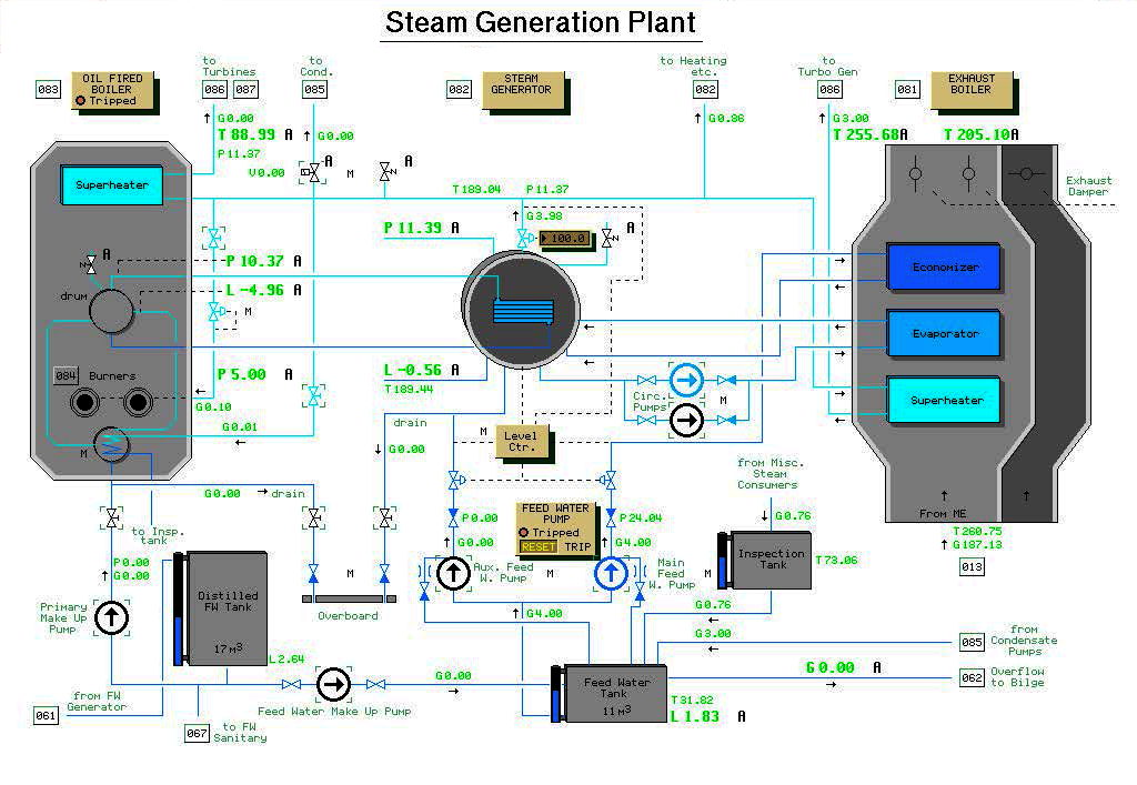
Η εγκατάσταση παραγωγής ατμού αποτελείται από έναν Λέβητα Καυσαερίων (Exhaust Gas Boilet / Economizer) και έναν Βοηθητικό Λέβητα (Auxiliary Boiler / Oil-Fired Boiler), οι οποίοι συνδέονται μέσω μιας κοινής ατμογεννήτριας. Συχνά, αυτή είναι ενσωματωμένη στον βοηθητικό λέβητα ως δευτερεύον τύμπανο τοποθετημένο πάνω από το πρωτεύον (λέβητας διπλής πίεσης).
Ο ατμός από το πρωτεύον σύστημα του Βοηθητικού Λέβητα (Auxiliary Boiler / Oil-Fired Boiler) συμπυκνώνεται σε νερό μέσα στην ατμογεννήτρια και επιστρέφει με τη βαρύτητα στο πρωτεύον τύμπανο. Το νερό στην ατμογεννήτρια (δευτερεύον τύμπανο ατμού) ρέει με εξαναγκασμένη κυκλοφορία προς το τμήμα του εξατμιστή του Λέβητα Καυσαερίων (Exhaust Gas Boiler / Economizer) και ένα μείγμα νερού-ατμού επιστρέφει στο δευτερεύον τύμπανο.
Το πρωτεύον σύστημα νερού είναι ερμητικά σφραγισμένο και κανονικά δεν υπάρχει κατανάλωση πρωτεύοντος νερού. Ωστόσο, εάν η πίεση του πρωτεύοντος ατμού αυξηθεί τόσο ώστε να ανοίξει η ασφαλιστική βαλβίδα ή αν συμβεί διαρροή νερού, η στάθμη του πρωτεύοντος τυμπάνου θα μειωθεί. Η αναπλήρωση του πρωτεύοντος νερού επιτυγχάνεται με την εκκίνηση της αντλίας αναπλήρωσης (primary make-up pump) και το άνοιγμα της αντίστοιχης βαλβίδας.
Σύστημα Τροφοδοτικού Νερού και Έλεγχος
Υπάρχουν δύο αντλίες τροφοδοτικού νερού για το δευτερεύον σύστημα. Το νερό από την κύρια αντλία (main FW pump) προθερμαίνεται στο τμήμα του Economizer του λέβητα καυσαερίων πριν εισέλθει στο δευτερεύον τύμπανο, ενώ το νερό από τη βοηθητική αντλία (auxiliary FW pump) πηγαίνει απευθείας στο δευτερεύον τύμπανο. Η βοηθητική αντλία χρησιμοποιείται μόνο για υψηλή παραγωγή ατμού (άντληση φορτίου) και έχει περίπου 5πλάσια δυναμικότητα από την κύρια αντλία.
Η στάθμη του νερού στο δευτερεύον τύμπανο ελέγχεται από έναν PID ελεγκτή στάθμης. Και οι δύο αντλίες τροφοδοσίας σταματούν (trip) σε πολύ υψηλή στάθμη νερού (high-high) στο δευτερεύον τύμπανο για την προστασία των καταναλωτών ατμού από το πλήγμα νερού (water strike).
Έλεγχος Θερμότητας και Συμπυκνώματα
Η μεταφορά θερμότητας στον Λέβητα Καυσαερίων ελέγχεται από κλαπέτα καυσαερίων (dampers). Η θέση τους ρυθμίζεται αυτόματα από έναν PID ελεγκτή, ελέγχοντας έτσι την πίεση του δευτερεύοντος ατμού.
Τα συμπυκνώματα επιστρέφουν σε μια δεξαμενή φίλτρου/επιθεώρησης (condensate filter/inspection tank) και στη συνέχεια στη δεξαμενή τροφοδοτικού νερού (feed water tank). Όταν ο Βοηθητικός Λέβητας (Auxiliary Boiler / Oil-Fired Boiler) λειτουργεί, υπάρχει συνεχής κατανάλωση νερού λόγω της ροής ατμού για τη νεφελοποίηση (atomizing) του καυσίμου στους καυστήρες. Η αναπλήρωση γίνεται από τη δεξαμενή απεσταγμένου νερού (distilled water tank).
Συντήρηση και Εκκαπνισμός (Sootblowing)
Η δεξαμενή τροφοδοτικού νερού και η δεξαμενή επιθεώρησης παρουσιάζουν θερμικές απώλειες προς το περιβάλλον και ψύχονται αν σταματήσει η ροή. Η θερμοκρασία εισόδου συμπυκνώματος θεωρείται σταθερή (80°C).
Εάν οι επιφάνειες θέρμανσης λερωθούν, χρησιμοποιείται ο εκκαπνιστής (sootblower):
• Ο εκκαπνιστής του Βοηθητικού Λέβητα λειτουργεί με δευτερεύοντα ατμό.
• Ο εκκαπνιστής του Λέβητα Καυσαερίων / Economizer λειτουργεί με αέρα υπηρεσίας (service air).
Η λειτουργία του εκκαπνιστή στον λέβητα καυσαερίων αντιπροσωπεύει ένα πολύ βαρύ φορτίο για το δίκτυο αέρα υπηρεσίας του πλοίου κατά τη διάρκεια της χρήσης του.

